![knowledge-base-header-bcn3d-logo.png]](https://support.bcn3d.com/hs-fs/hubfs/Knowledge%20base/Header/knowledge-base-header-bcn3d-logo.png?height=40&name=knowledge-base-header-bcn3d-logo.png)
Congratulations! You just got yourself a 1.75mm upgrade kit to turn your printer into an Epsilon X.
Before starting with the upgrade, there are some steps that differ between Epsilon G1 and G2 models. The quickest way to identify your printer model is to check if it uses an X driver or an adapter board.
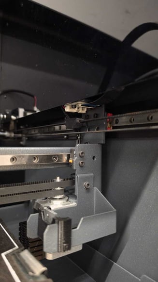 |
G1 DRIVER |
|
G2 ADAPTER BOARD
|
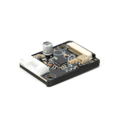
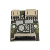
Now that you know what you are working with, let's begin the installation!
Setting everything up


The only extra tools you'll need for the installation are listed above. The rest are provided in the kit.
 During the installation, you'll have to remove some screws and nuts that will later be used to install the kit, so before starting, make sure you have a space to organise your hardware.
1. The first step is to unload the filament from your printer. To do it, go to utilities/Filament/unload. Once both sides have been unloaded, remove the spools from the printer to work more comfortably.
2. Go to the Utilities/Maintenance/move printing platform menu to Lower the platform, leaving a gap of around 10 cm between the inner cover and the platform.
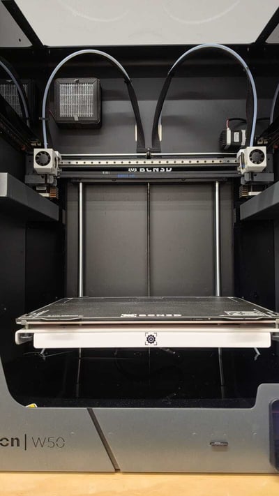
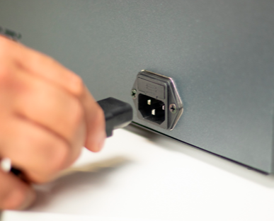
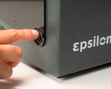
3. Turn off the printer and unplug it from the power outlet.

|
|
 |
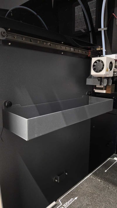
4. Unscrew and remove both purge buckets.
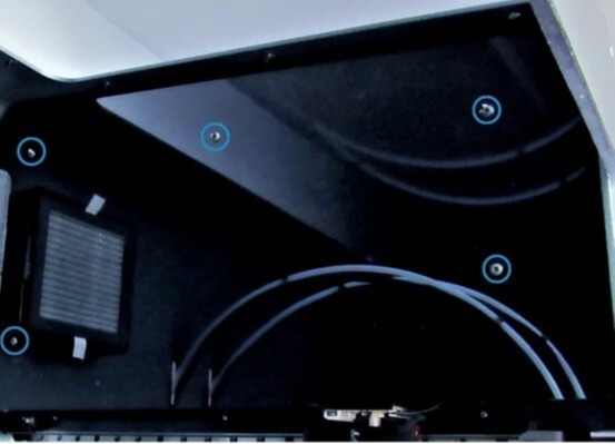
5. Remove both internal side covers, as well as the printer's top cover in order to work comfortably.
 |
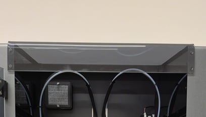 |
Keep in mind that the top cover is held with nuts on the inner side, so make sure you are holding them before removing the screw, to avoid losing them inside the printer.
Removing the extruders and the filament runout sensor (FRS)
1. Remove the rear extruder cover.
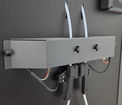
Depending on the cover version that your printer has, you may not be able to install it again. In that case, this area of the printer will remain uncovered
2. Disconnect the motor cable from both extruder motors.
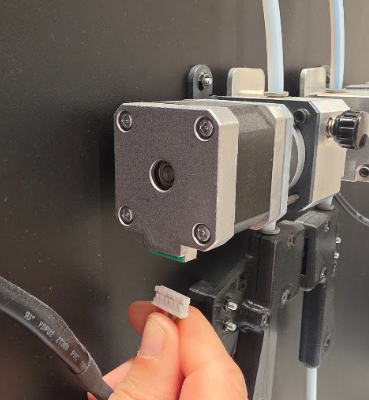
3. Remove the coupling clips from the extruder motors output and detach the Bowden tubes.
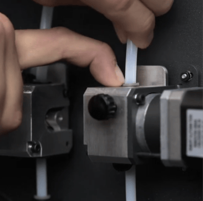
4. Remove the lower coupling clips from both FRS input, and detach the Bowden tubes.
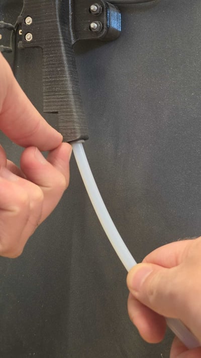
5. Remove the nuts holding the FRS and the extruder motors to the printer's structure, then remove each extruder motor + FRS assembly.
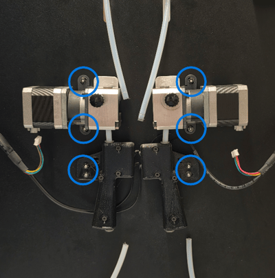
6. Disconnect the Faston connectors from the FRS switch. The FRS switch cables have no polarity, so they don't need to be labelled.
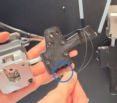
7.Lastly, remove the printed FRS spacers from the printer's structure.
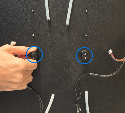
You can put this whole assembly aside as it won't be used for the updgrade.
Removing the XY carriage
1.Detach the bowden tubes from the hotends and remove the cable clips holding the bowden and the flat cable together. Once this is done, you'll be able to fully remove both bowdens from the printer. You can set these aside as they won't be used for the upgrade.
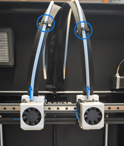
2.Unplug the X motor cable and the endstop cable from the X drivers (G1) ot the adapter boards (G2). There's no need to cut the zip ties holding the cables, as the whole assembly will be removed later on.
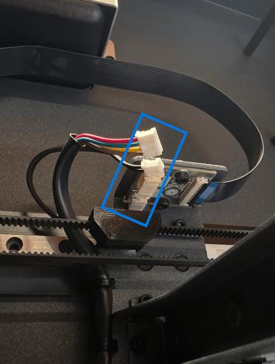
3.Unscrew the hotend cover from the pritning heads as well as any other printed parts holding the flat cable, in order to have it removed.
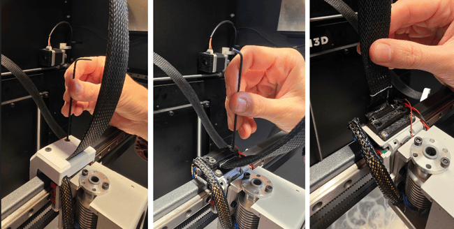
4.loosen the extruder board clip in order to unplug the flat cable. Once this is done, completely remove the printing head cover by either sliding it out of the cable. The tape holding the flat cable textile cover may not allow you to remove the hotend cover. In that case, you can break it, as it won't be used for the upgrade)
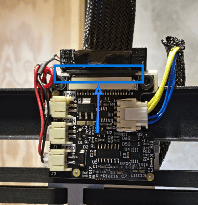
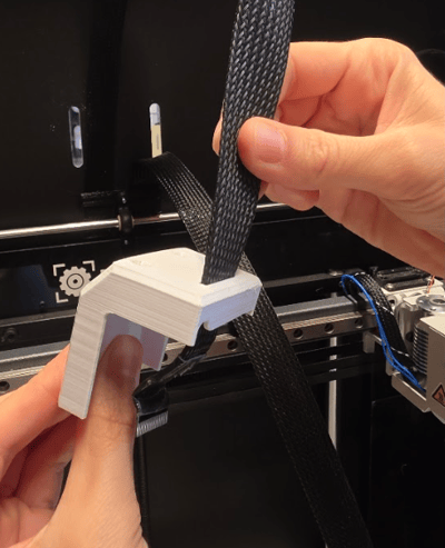
5.Unscrew the right side support from the printer's carriage.
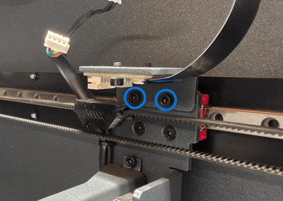
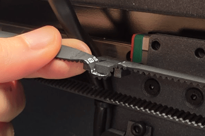
6. In case it is installed, remove the printed part covering the belt and the strap attachment, and then detach the belt from the strap attachment.
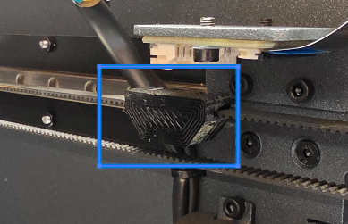
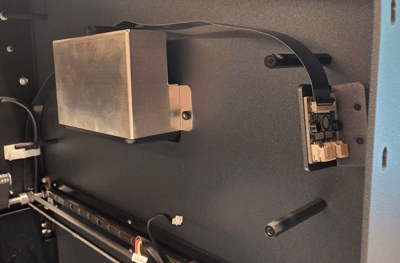
You can leave the driver / adapter board assembly hanging on the side panel screws in order to work comfortably:
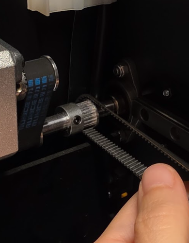
7.Remove the belt from the rear pulley by sliding it out while rotating it, and place it to its right side.
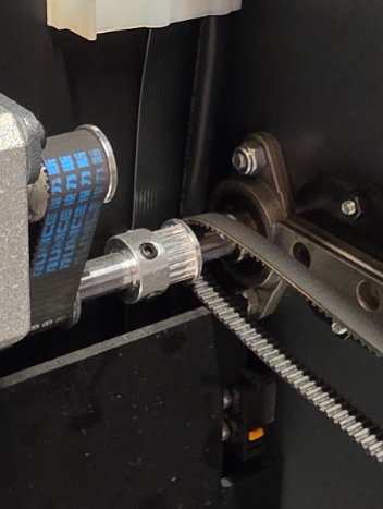
8.Remove the screws holding the carriage to the right Y axis bearing, and leave the carriage hanging on the loose Y axis belt.
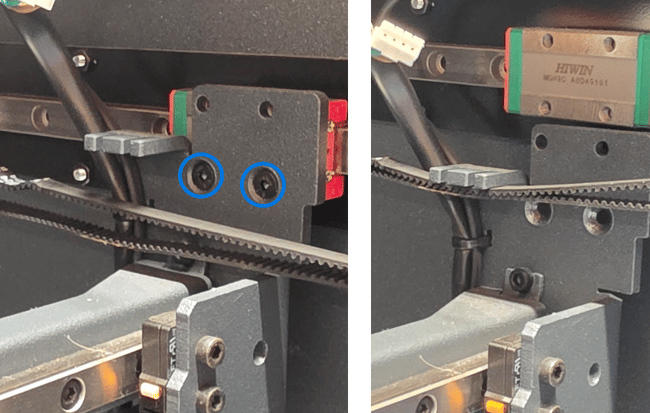
9.Hold the carriage with one hand, while removing the three screws holding it to the left side of the printer. Once this is done, remove the full carriage assembly from the printer.
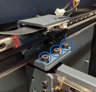
It's recommended to perform step 9 with the help of a second person
Installing the new filament runout sensors (FRS)
1. Locate the two extension boards included in the upgrade kit and install them in the rear panel of the printer's structure, as shown in the image below, using the previously removed screws.
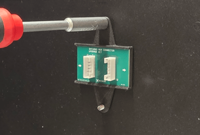
4x DIN934 M3
4x DIN6798 M3
2.Once this is done, conect the left and right extruder cable to the corresponding ports in the extension boards. (use the port that's closer to the cable)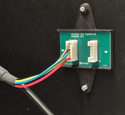
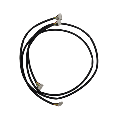
3.locate the extruder cables included in the kit, connect them to the remaining port in the extension boards and leave them hanging behind the printer.
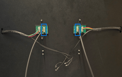
4. Plug the faston connections to the filament sensors included in the kit, using the conection points on the edges and avoiding the central one. Keep in mind that the cables have no polarity, so you can connect each one in any of the two available pins.
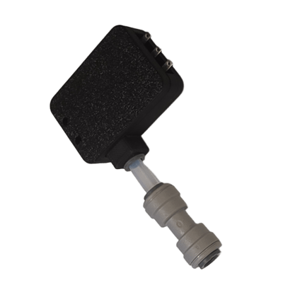
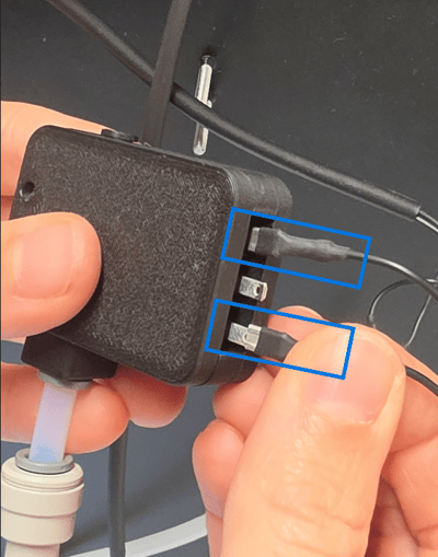
5.Attach the filament sensors to the printer's structure, using the previously removed screws.
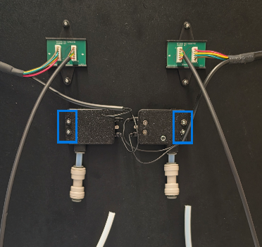
4x DIN 934 M3
4x DIN125 M3
6.Attach the 2.85mm lower bowden tube to the coupling connector.
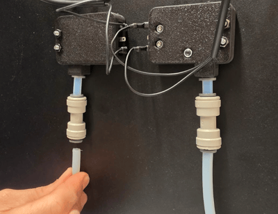
7.Attach the 1.75mm bowden tubes included in the kit to the filament sensor output. Do not route them inside the printer yet, as they will interfere with later adjustments.
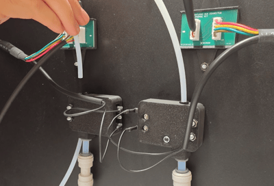
8.Install the extruder rear cover if possible. Keep in mind that one model is not compatible with the upgrade kit.
Preparing the carriage
1. Select the correct X motor cable version for your printer.
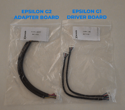
2. Take the carriage out of the box, and position the carriage as shown below. Connect the motor cables to the X motors, routing them alongside the X endstop cable (already installed in the kit), and holding them with the included zip ties.
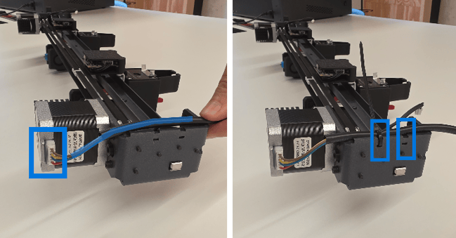
Notice that if the endstop cable is shorter, you will not be able to route it through the lower and upper zip tie. In that case, just route it through the upper one.
3.Install the brass wipers included in the kit on each side of the carriage, using the screws included in the kit
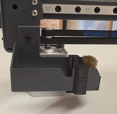
2x DIN912 M3x6
2x DIN125 M3
Installing the carriage
1. Place the hotend flat cables over the printer's structure top, so that they don't interfere during installation. Then position the carriage inside of the printer, leaving the right side hanging from the Y belt, while holding the carriage from the left side.
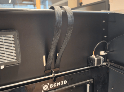
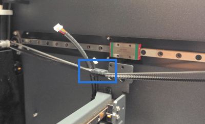
2. Allign the carriage, and Install the central screw on the left holder, without tightening it completely.
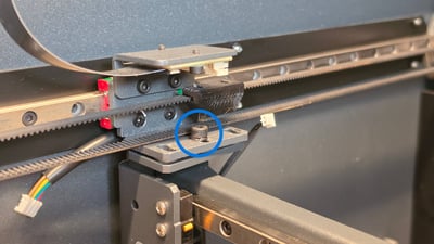
3. Install and tighten both screws on the right side support, assembling the carriage to the ball bearing.
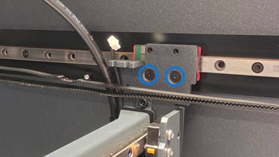
4. Install the remaining screws on the left side of the carriage, without tightening them completely.
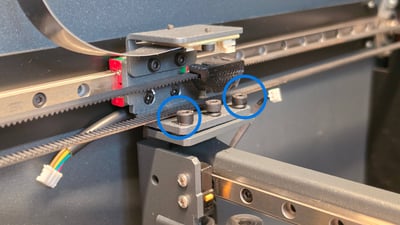
Installing the Y belt and adjusting the parallelism of the carriage
1.Attach the right Y axis belt to the right strap attachment.
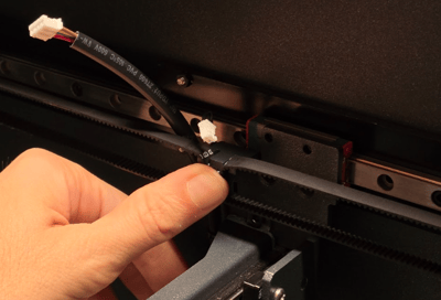
2.Loosen both hollow screws holding the Y pulley on the rear bar, without removing them completely
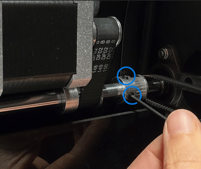
3.Move the carriage to the front of the printer, until both printing heads are in contact with the frame
4.Place the pulley spacer included in the kit, between the motor pulley and the belt pulley in order to set it to the right distance. Move it if needed, and then, tighten one of the hollow screws. Remove the spacer and keep it close, as it will be used in the coming steps.
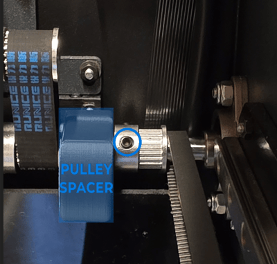
5.Install the belt in the pulley by placing it over the pulley's edge, and rotating it manually so that the belt slips in.
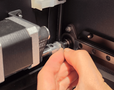
6.loosen the previously tightened pulley's hollow screw
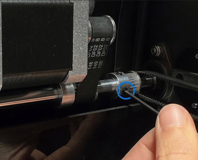
7.Now move the carriage to the back of the printer, leaving a few cm clearance, and Install the spacers included in the kit on each side, as indicated below. This will be used to adjust the paralelism of the carriage.
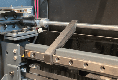
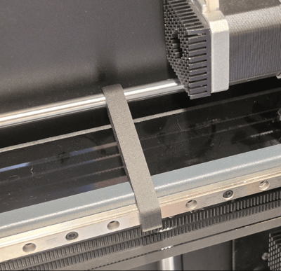
8.Place the pulley spacer between the motor pulley and the belt pulley then tighten, the visible hollow screw.
9.Tighten the remaining screws holding the carriage to the left side of the printer structure
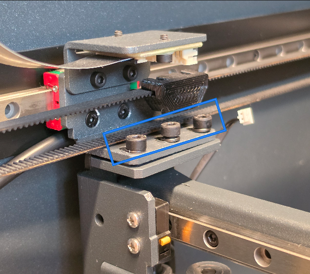
10.Remove the spacers (x3) used to correct the parallelism.
11.Bring the carriage forward in order to access the remainng pulley's hollow screw, and tighten it.
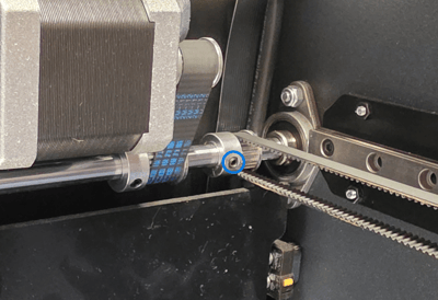
Wiring
1.Connect the X endstop and motor cables to the driver or adapter board. Make sure these are routed through the tie wraps as exlained in previous steps, then install the driver (G1) or the adapter board (G2) support on the right side of the carriage, using the previously removed screws.
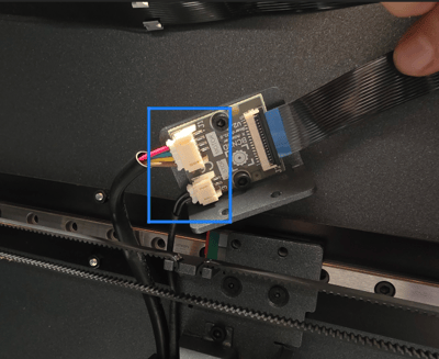
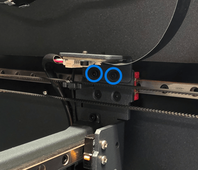
2x DIN 912 M3x8
2.Route the bowden tubes and extruder motor cables from the back of the printer to the front through the slots on the rear cover of the printer.
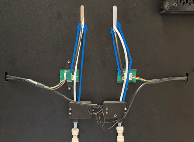
3.Connect the extruder motor cables to the bondtech motors on each printing head.
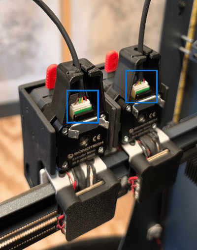
4.Remove the extruder board covers. They should come out with a "click" sound.
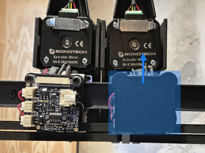
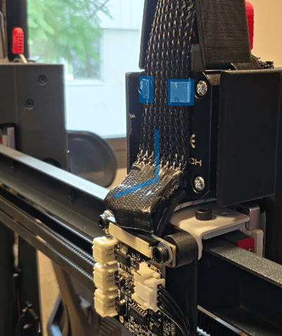
5.Route the cable through the upper cover space, slighlty bending the cable in a U shape so that it fits in the dedicated slot.
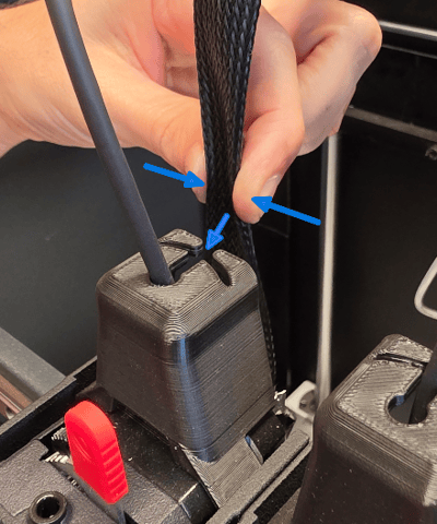
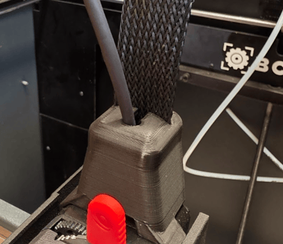
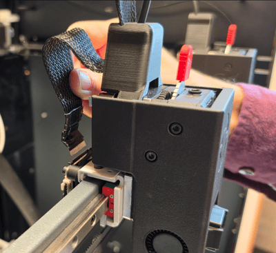
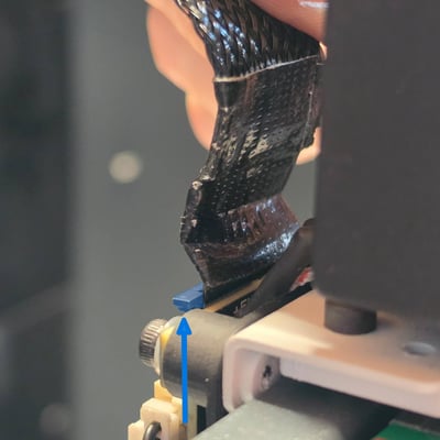
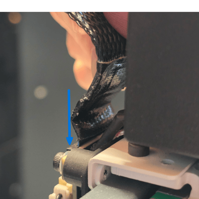
6.Connect the flat cable to the extruder board by loosening the extruder board clip. Make sure the cable is properly connected. You can do this step from the front of the printer, or the back, using a stool to access the printing head from behind the printer.
In order to make this easier, pull some cable so that you have more margin to connect it, as seen in the pictures below:
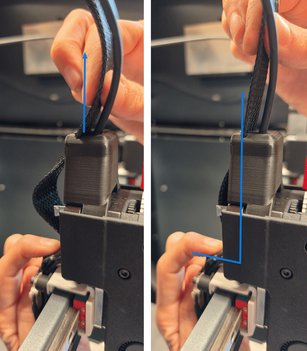
7.Press the flat cable down so that it follows the shape of the printing head, creating a 90º angle, and then secure it with the metal clamp.
8.Put the extruder covers back in place. You should hear a click sound once the cover fits correctly.
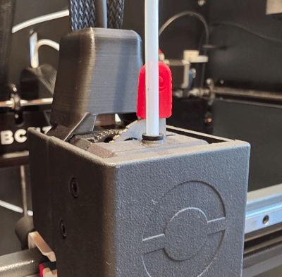
9.Connect the previously routed 1.75mm bowden tubes to the printing head.
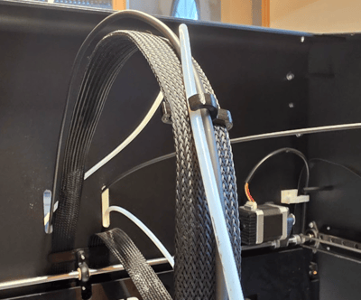
10.Install the cable clips included in the kit in the flat cable, routing both the bowden tube and the extruder motor cable through the dedicated slots.
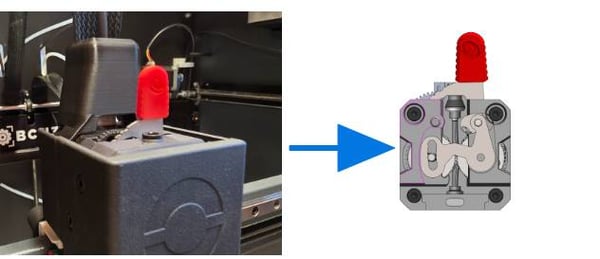
11.Correct the position of the extruder motor clamp as shown in the picture if needed.
Install the covers
Once this is done, the new hardware is fully installed, and you will just need to install the upper cover, the inner side covers and the purge buckets that have been previously removed.
Upper cover
14x DIN7991 M3x16
14x DIN9021 M3
14x DIN934 M3
Side covers
10x DIN7380 M3x10
Updating the FW
Once the upgrade is installed, insert the included SD card in the SD reader, and turn on the printer.
The new FW will be detected and the update procedure will start.
Once the process it's over, remove the SD card.
Stratos