Introduction
Having a look on the BCN3D printer files, you may discover many features and design details that will create tons of questions. Why did they get a dual independent extruder? Why an aluminium frame? Custom electronics?
We didn’t want to just upload a CAD file, some gerber, and firmware files. We wanted to give to the community an explanation of the solutions we chose, the “behind the scenes” of these solutions.
When we started working on the RepRap project under the name RepRapBCN in 2011, visitors coming to Fundacio CIM were amazed by the simplicity of those little machines made with rods, bolts, and nuts. They were able to see something not visible in the big rapid prototyping machines: How the part is made.
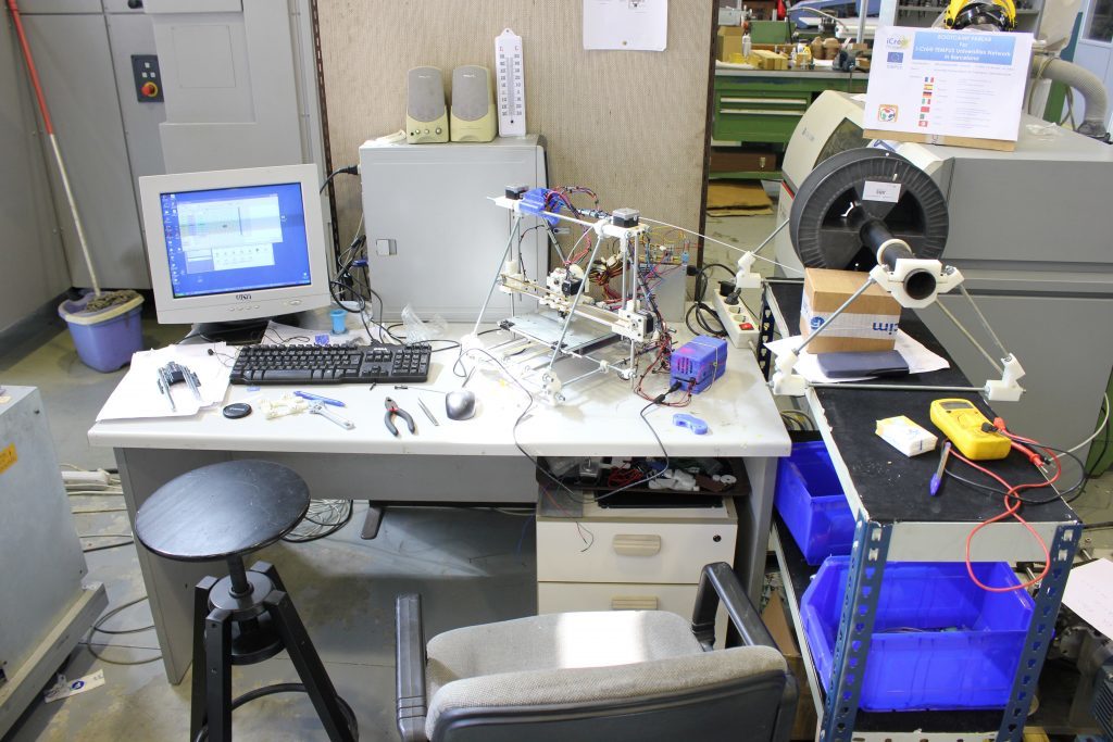
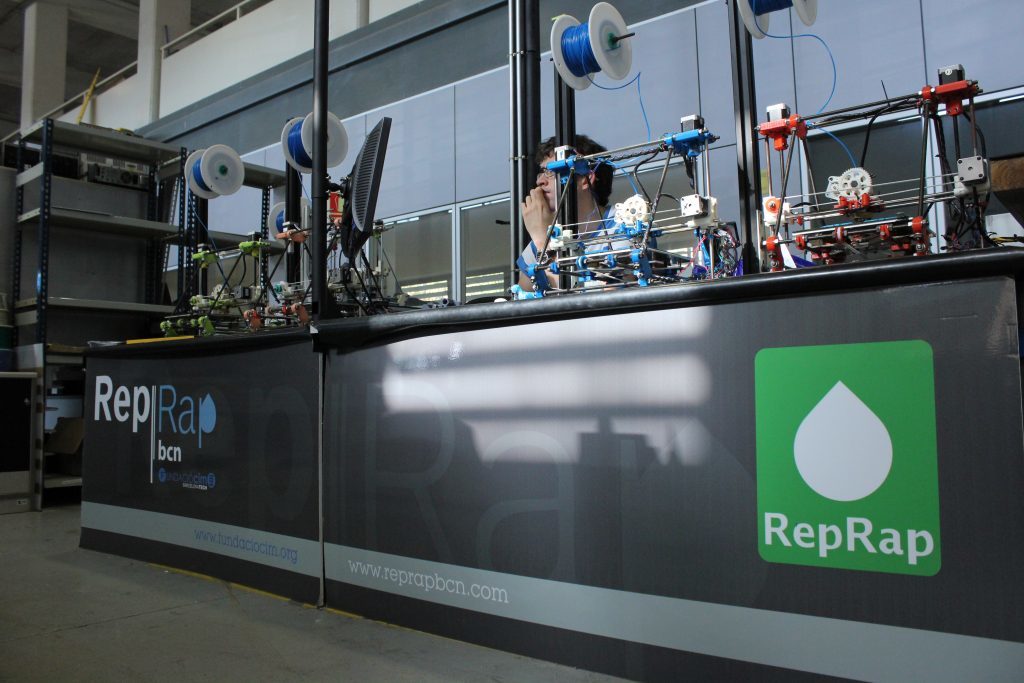
But they also saw something undesirable: Those RepRap Machines were unreliable when used intensively. Moreover, the quality of the outcoming parts was far away from the professional technologies results. In addition, there were serious geometric limitations, so many real-world parts couldn’t be produced. None of those visitors could become users: they did expected better features.
The influence of the big sisters, the SLS and the SLA, as well as the suggestions of the visitors, made us try to solve those problems and shorten the distance between professional rapid prototyping machines and the RepRapBCN machines. Before starting to invent new machines, though, we would try to get the best of the RepRap concept.
The BCN3D+ was designed in 2013. An upgrade was available for experimented users to start printing with two extruders. At that moment it was not common for a printer with two hotends, but there was enough information in the RepRap project to get the mechanics and the firmware adaptation done. So we did it.
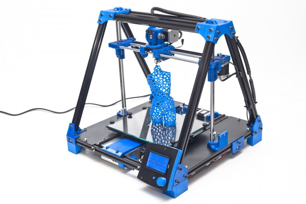
The results were a little disappointing. We achieved the fact of printing with two materials but we had many other problems related to the process: Carriage was heavy and the quality in the final part was lower than the one obtained from single extruder printing. The calibration process was complex and not understandable for new users. Finally, the oozing from the idle nozzle affected the part when the other nozzle was working.
As you may know, by that time, 3D printing was the most followed technology and the hype was extreme. By the middle of 2014, we realized that the BCN3D+ was not able to fulfill the new customers that were embracing the technology. So we started a new design.
It is funny now to remember the first concept for the Sigma: A cubic machine made in aluminum profiles. Something that was clearly an upgrade of the BCN3D+.
But the disrupting point was that our chief engineer found a video on youtube of somebody printing with independent nozzles. That concept was able to solve many of the problems we had with the dual extruder upgrade we tried in the BCN3D+. Finally, we had found something that would possibly make those visitors become future users and the big sisters RP machines less big. We only had to do it reliable when sold in large numbers. Only…
All the design process was conditioned by the dual printing concept. We needed something more sturdy than assembled aluminum profiles, so we designed this aluminum welded frame. We needed an easy calibration for the more complex architecture, then we added an LCD touch screen able to guide the user through the process. We needed electronics able to rule 6 axis and be reliable so we designed custom electronics… Everything on the machine is intended to make this independent dual extruder easy to operate, understand and maintain.
In the specific repositories, you will find technical details on those solutions that had made this dual extruder system possible and the files will support this explanation.
Mechanics
What’s hold in this repository?
This repository will hold all the information about the Mechanics of the BCN3D Sigma.
As a declared Open Source organization, it’s in our mission to release all the original design files to you to be able to learn, reuse and improve. Open Source not only means code, it also concerns hardware.
We’ve managed to design and manufacture the BCN3D Sigma thanks to our previous experience in the 3D printing industry, the ideas coming from the community, our engineering background, and a narrow collaboration with our suppliers. Our goal is to justify the decisions we took and share the know-how we acquired so far.
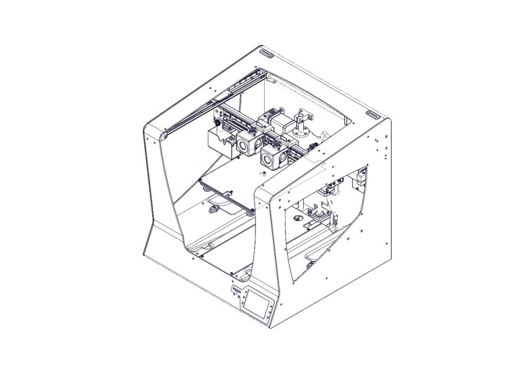
We also provide the source files for those who want to check the core of the BCN3D Sigma. You can consult both the CAD files and the technical drawings.
During the concept design stage, we set a clear target that determined the whole design and decisions: The BCN3D Sigma is a professional printer.
Aesthetics
It has to look like professional equipment. Our previous printers were made with aluminum extruded profiles and plastic printed parts. That made sense for printers oriented to makers or schools, sold as a kit. But, in this case, the aesthetic was a major player. For this reason, we adopted a welded aluminum frame, which allows the Sigma to be a unique and attractive 3D printer.
Multimaterial
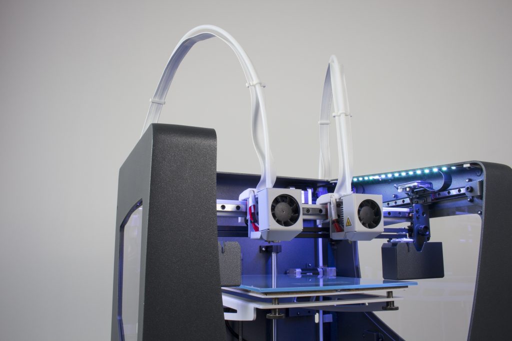
As a professional printer, it has to print as many materials as possible. Not only for engineers, who require tough -or flexible-, functional polymers but also for designers who need the aesthetic component. However, the material is not the only limitation. Complex geometries, overhangs, and 3D printing don’t get along. So we wanted the Sigma to be a real solution for those users who need to print with support as a must. In conclusion, Sigma is the first and only commercial 3D printer with an Independent Dual Extruder (IDEX) system, which avoids all the side problems dual extrusion may cause.
High Quality
The 3D Printing industry is maturing. Users are more and more demanding and 3D printing must be a solution, not a headache. For this reason, the Sigma has to be a reliable piece of engineering, easy to assemble, maintain, and capable to print seamlessly high-quality objects, no matter how complex they are.
High Capacity
Real-life and functional parts are not always small. A big printing volume is a great advantage for a professional 3D Printer although Sigma intends to be a desktop-sized printer. Allocating all the items and devices inside the frame, while granting ease to use and optimizing the axes structure was a key goal.
We faced dozens of challenges during the design process.
Below we describe some of them:
Frame
Probably the biggest challenge. First, we thought of a chassis made of profiles and then cover it. But then realized the cost of materials for that solution would be high enough to look for alternatives that could contribute more in the aesthetic field, even if that could be a bit more expensive. On the other side, we wanted the Sigma to be an accessible printer, wide and open in order to ease the handling and operation. So we decided to explore the option of designing a unibody frame where all the mechanical components were mounted on and with a wide frontal overture.
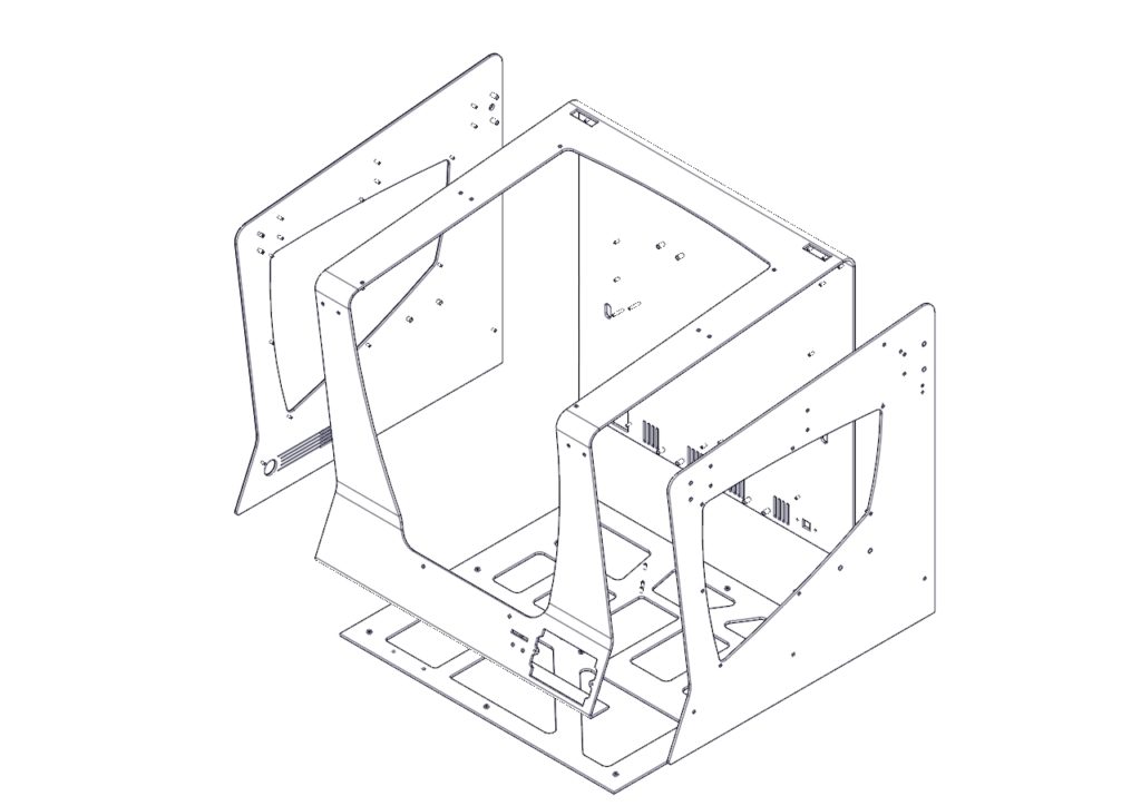
First, we had to decide between using aluminum or steel. Steel offers many advantages: It’s a very stiff metal, great to build structures, and precise mechanical systems. In addition, it’s easy to work with and cheap. But it’s -really- heavy. We contemplated the option of using a thinner metal sheet of steel for the frame. After ordering a prototype, we dismissed the idea, though. Still, it had a great mechanical behavior and relatively low weight, the feeling of touching a thin metal sheet (1.5mm) was unpleasant because it felt like a cutting edge. And it didn’t look sturdy. So to achieve both a reliable look and a pleasant contact, we needed to go up to 3mm thickness. But then the shipping costs would be absurdly high and the handling, a constant hassle -both during the assembly process and for the final user.
Aluminum, on the other hand, provides lightness and a smooth and sturdy look. But it’s more expensive as a material and it’s harder to laser cut and weld. After balancing the pros and cons, we bet on the aluminum option -although we had a plan B.
The second big issue to manage was the manufacturing process. We contemplated two different ways to do it: either manufacture the frame by parts and screw them all together in the assembly line or weld the frame. Welding aluminum is hard and the welding process itself has some thermal and geometric implications that have to be considered. But it allows reducing the assembling time dramatically while it outsources a key process.
As an alternative, designing the frame as separate parts to screw together was considerably cheaper – as you save a handmade process such as welding and polishing. But the assembling of the frame and adjustment could be very delicate and incompatible with our production tag time. So the overall cost wouldn’t be that different in both options. The aesthetic component, though, would be very penalized with this alternative, because we would need to add dozens of screws to the frame.
For these reasons, we finally opted for a welded structure. We sat hours with our supplier discussing the best way to design every single part in order to grant a proper alignment between the faces that would hold the axes. Furthermore, we also studied the mechanical behavior of the frame with some CAE studies, simulating stress and deformations during standard usage.
High-quality components
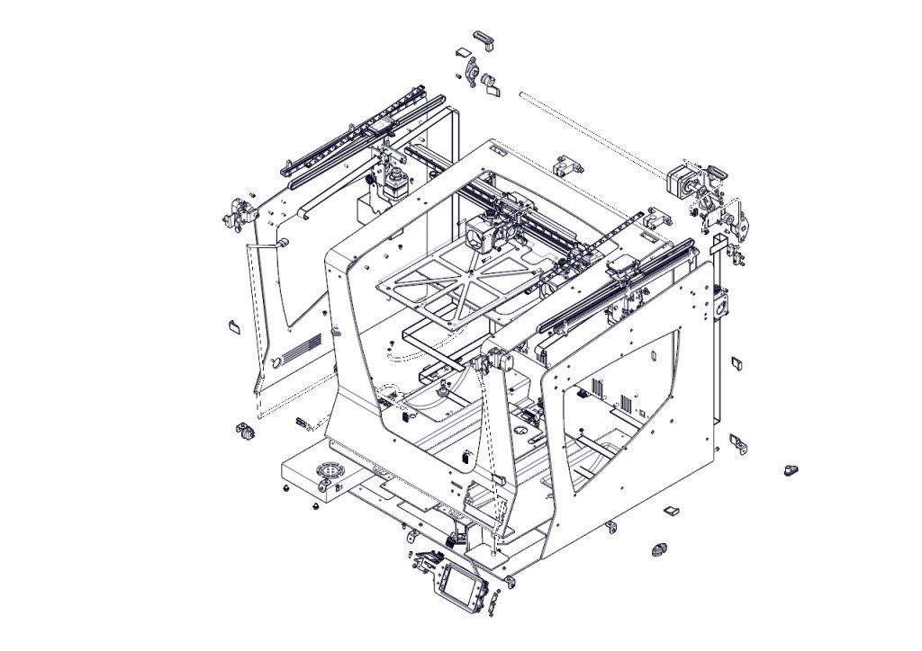
A good frame is not enough to achieve amazing results. In such precision equipment as the Sigma, all the mechanical components play a key role. Due to the product requirements in terms of size and use of the internal space of the printer we had, we opted for an axes structure with the toolheads moving in the XY plane and an up and down moving Z-axis.
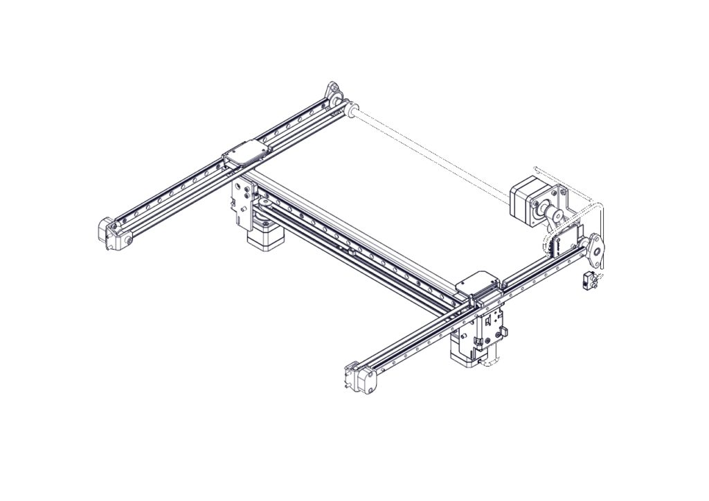
With the XY plane decided to mount high precision linear guides. Despite its cost is slightly higher than a system based on rods and bearings, the linear rails offer a professional look, easy assembling, and a compact package.
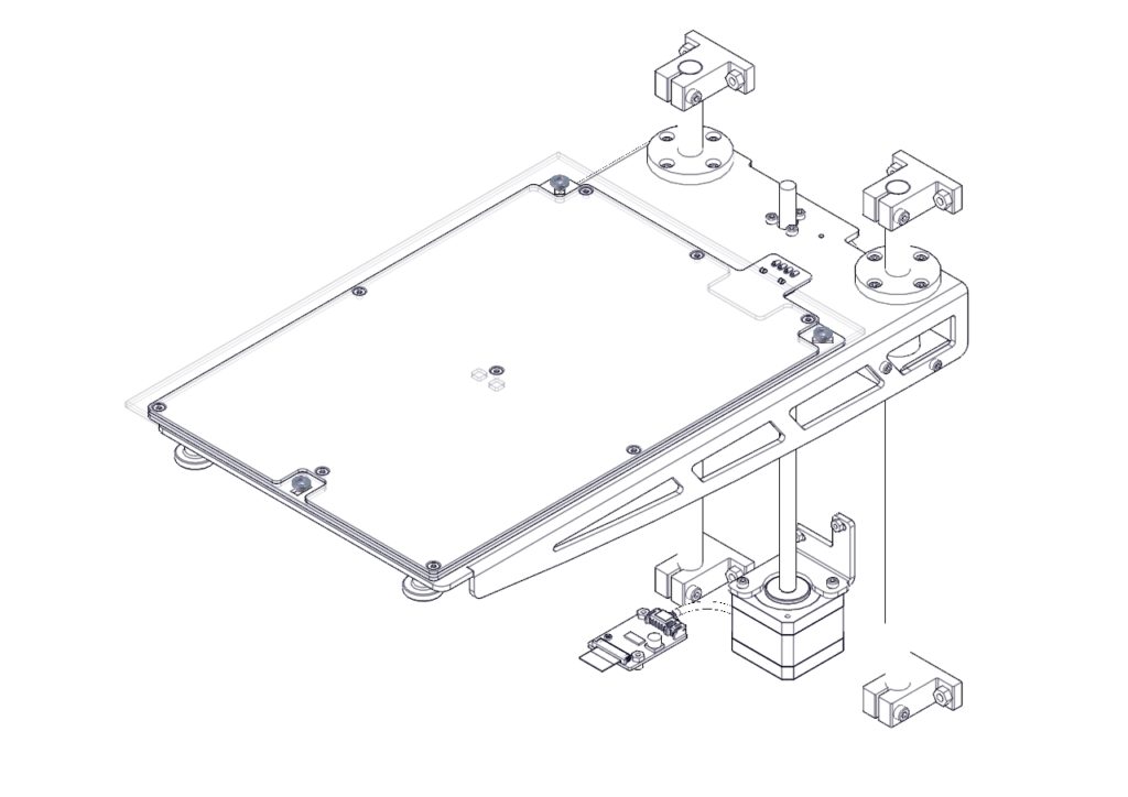
Regarding the Z-axis, we were aware of the importance to have a robust guide system in order to avoid classic artifacts in printed parts related to a bad Z performance, such as Z wobbling. We also had experience using couplings to connect the actuator with the leadscrew and we knew that a bad assembling could cause poor quality results. With this background, we chose to use Ø12mm guide rods and a stepper motor with an inserted leadscrew. The whole system provides high repeatability and accuracy.
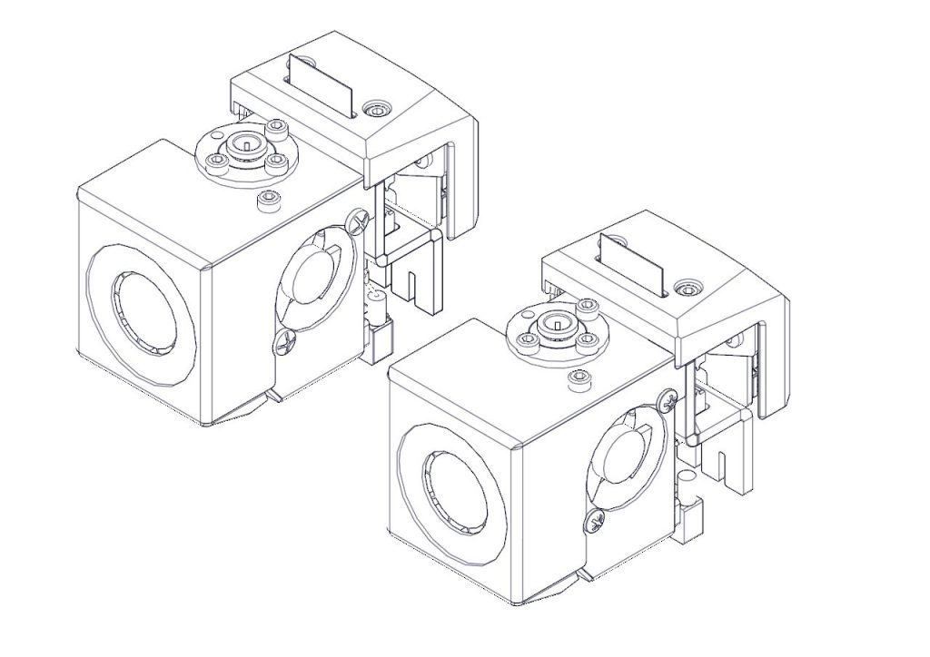
Independent Dual Extrusion
A 3D printer with such a specific feature increases the design unknowns and multiplies the components. Not only do the firmware and the electronics need to be highly customized, but also mechanically there are some decisions to take.
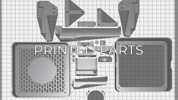
First of all, because of the multiple components to hold, the internal parts tend to be more complex than other printers. So we decided to use aluminum sheet bending technology to manufacture the inner parts. As the manufacturing tolerances are acceptable for the purposes we intend and the technology is cheap and easily scalable, we considered the technology optimum.
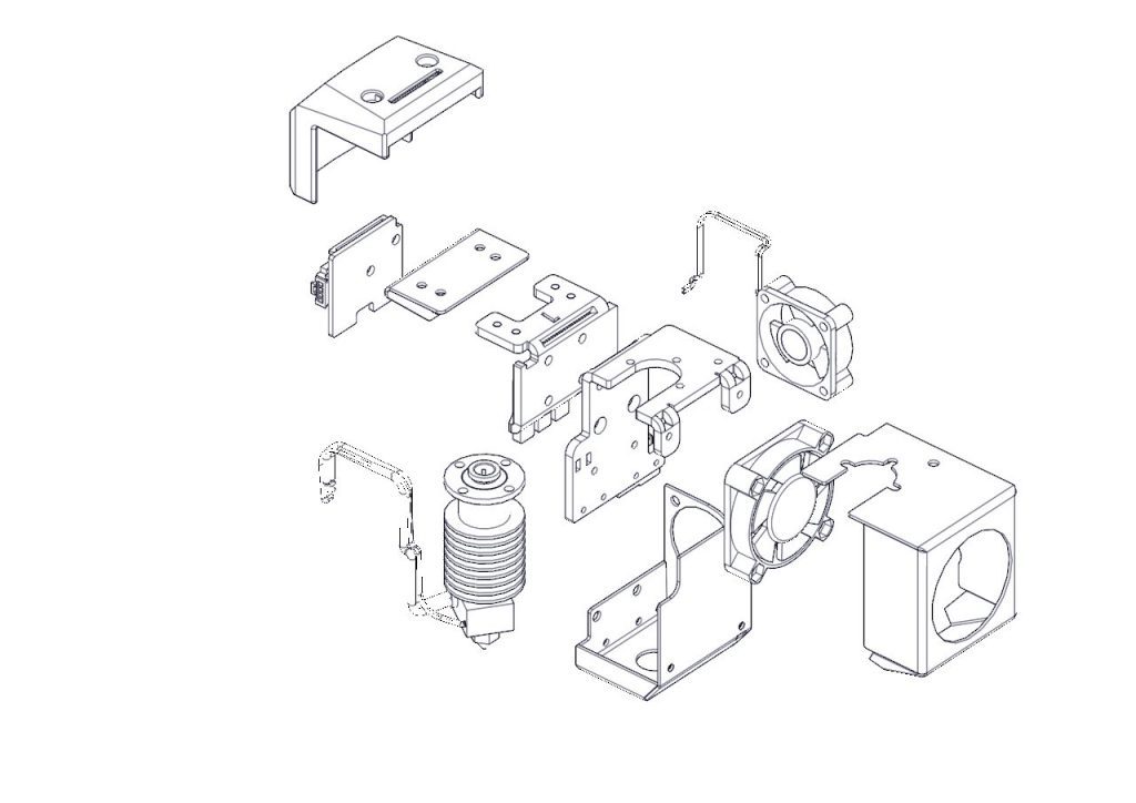
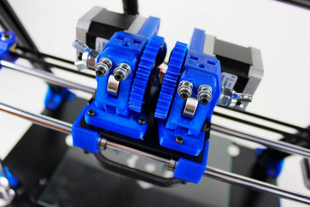
Two independent Extruders means having an extra moving stepper for the second toolhead, and the extra toolhead itself. On the other hand, when printing with both extruders it’s important to have a bucket to purge the idle hotends before start printing the model again. All this parts add weight to a moving element, which is a problem to print fast because the high inertias may worsen the print quality. So we designed the X and Y Axis as light as possible, saving as many grams as possible with every single component. Not only weight is important when doubling the toolheads, but also space. So we decided to adopt a bowden-based feeding system and miniaturize all the items as much as possible.
Big Printing Volume
The BCN3D Sigma features a 210x297x210mm printing volume. In order to provide such a big volume and a free space on both sides to park the idle toolhead, but still have a desktop-sized printer, we had to reorient the Z platform. The main issue to solve, though, was granting the stiffness of the structure with a big overhang of more than 300mm.
To prevent vibrations, we adopted high-quality bearings with low clearance and we designed and simulated a custom metal sheet structure, which allows getting great quality prints with a smooth surface despite the big overhang.
Electronics
As a declared Open Source organization, it’s in our mission to release all the original design files to you to be able to learn, reuse and improve. Open Source not only means code, but it also concerns hardware. This repository will hold all the information about the Electronics of the BCN3D Sigma.
We’ve managed to design and manufacture our custom Electronics for the BCN3D Sigma in many ways thanks to the community and other Open Source Hardware projects. BCN3D Electronics is a mashup between the Ultimaker 2 Board, the Megatronics v3.0, and some others…
Concept design
The BCN3D Electronics is intended to be modular and custom fitted in our BCN3D Sigma 3D printer and that’s why we made some design decisions.
- Stepper drivers out of the Mainboard. As the drivers generate quite a lot of heat, we’ve moved them nearest as possible to the corresponding stepper motor. If one fails, you just have to replace a cheap stepper driver board. This way, we’ve managed to fit an entire electronics system without a fan.
- FFCs everywhere. The BCN3D Sigma is an Independent Dual Extruder Printer so the Electronics support 6 Axis of movement. That's a lot of wires and wires take up some precious space. We decided to go with a Flat Flexible Cable solution that keeps things organized and it’s faster to assemble.
- 24VDC Power Supply. The performance improves as the whole Electronics runs cooler while maintaining a very low voltage system.
- Full Color Resistive Touch Screen. The electronics are compatible with 4D Systems Displays out of the box. We think the user should interact with an intuitive interface to be able to use the printer easily even without previous experience in 3D printing.
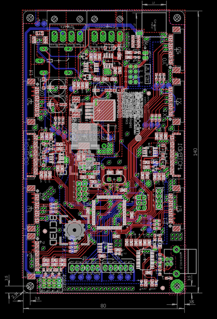
Boards
- Mainboard: This board holds the microcontroller, the 5V switching power supply, the power outputs, and the thermistor inputs. It has a USB interface for upgrading the firmware and communicating with the printer via serial port.
- Stepper Driver: We carry the well-known DRV8825 stepper driver from Texas Instruments. It’s able to supply plenty of power for all the types of stepper motors in the BCN3D Sigma.
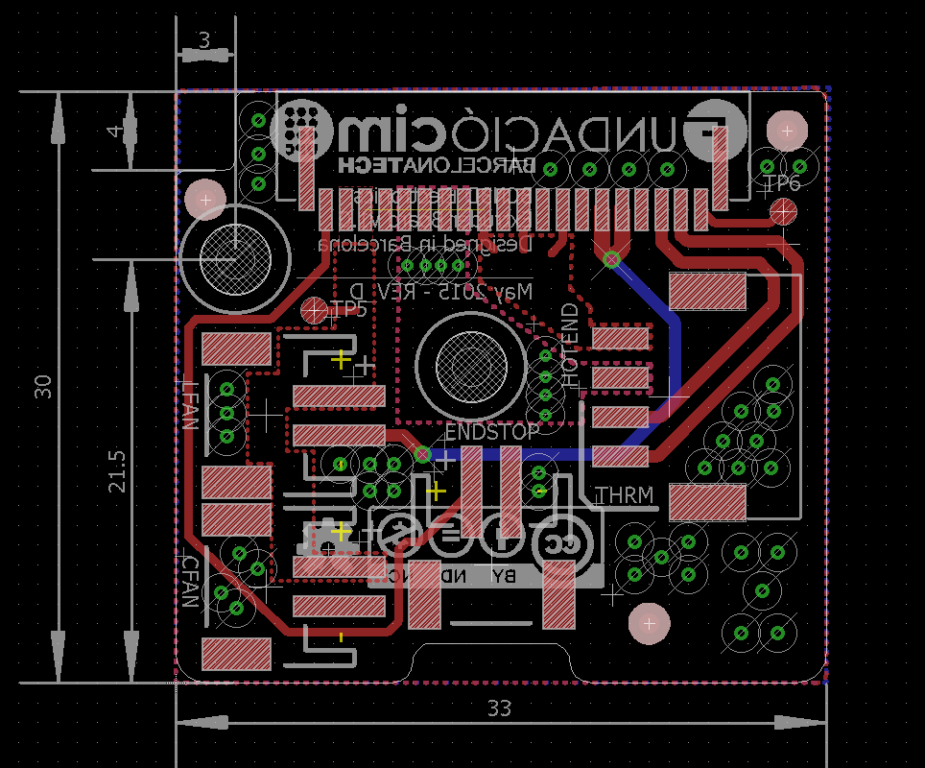
- Extruder Board: It’s a simple interconnection board between the Mainboard and the components of the hotend assembly. With just one Flat Flexible Cable the microcontroller has control over the hotend, the thermistor and endstop readings, and the layer fan.
- Heated Bed: As the platform size of the BCN3D Sigma is quite big, we’ve made a custom A4 size heated bed achieve the performance required. It can heat up to 100ºC in about 6-8 minutes and keep that temperature for a long period of time.
Production
We strongly believe that using high-quality components has an effect on the electronics performance as well as the printer performance.
This is why we ensure components quality and control of the production process by designing and manufacturing in Barcelona. In this manner we iterate faster, reducing time to market.
Being in control of all the supply chain allows us to optimize designs and reduce costs.
Firmware
BCN3D Sigma Firmware based on Marlin
This is the repository that contains the firmware for the BCN3D Sigma 3D Printer. It’s based on the well-known Marlin but with some modifications.
This firmware was first programmed by Jordi Calduch then was Xavier Gómez and now Alejandro Garcia, and designed by Pedro Baños and Jaume Juan at BCN3D Technologies.
We’ve worked since the very first time with Marlin Firmware when designing the first BCN3D Technologies 3D printers. We’ve learned a lot of things along the way and we feel comfortable with it and that’s the main reason to implement it on the BCN3D Sigma.
The community is huge and the project is continuously updated.
We’ve made quite a few changes to adapt it to Sigma’s features. Here’s a list of some things we have implemented:
- Dual independent X extruders: one of the main features of the BCN3D Sigma is the Independent Dual Extruder system (IDEX). It lets you print in two colors or two materials and has the ability to print support structures for your complex geometries.
- Auto-level, auto-calibration of XYZ axis: the main concern about the IDEX system is how the user will calibrate the offsets between nozzles and the bed. We’ve designed a 3-point touch pattern in order to fine-tune the different axis offsets and everything is guided through the LCD display.
- LCD Touch Screen support: our goal is to get a Sigma in everybody’s hands and to do that we need to make it robust and easy to use. We think you don’t need to have previous experience in 3D printing to make gorgeous prints and adding an LCD touch screen makes things easier. We’ve designed a comprehensive interface with simple menus and icons to make using the Sigma a breeze. All the code is segmented to other people take a look at it and understand it.
- Insert/Remove filament: as the printer uses a bowden-based filament drive system, inserting and removing the filament is an inconvenience so there’s a button to load or unload the filament. The process, once again, is guided via the touch screen and it will take you only a minute. The filament is pushed right to the tip of the nozzle.
- Refined firmware for better printing experience: Marlin firmware is well-known in the 3D Printing community as a lot of printers take benefit from it. We’re not different but we’ve tried to optimize it and take a lot of things our printer doesn’t use. As some people know, because they follow our progress on GitHub, the code is being updated almost every day.
As we truly believe in Open Source development and we want to you know your machine, we document all the progress and keep track of all the issues and feedback.
Software
One of the pillars of 3D printing is the software that converts your .stl files into something your printer understands. Good software can really have an impact on the final results. That’s why we rely on the most used slicing engine and software, Cura by Ultimaker.
As the project is also open-source, we’ve managed to get the code and start customizing the interface to our needs and tweaking some parameters to improve the quality of the prints.
It’s a rough way but we’re learning a lot. Every day we understand more and more about why and how the printer behaves so we can keep on developing better products for you.
One of the features we’re proudest of is the automatic firmware upgrade. BCN3D Cura connects to your printer and compares your actual firmware version with the latest release on Github. If there’s a newer version, the software downloads it and guides you in the process of uploading it to the printer.
This channel let us release more versions making it easy for the final users to update their printers. There’s no need to mess around with Arduino or other stuff.
We currently support BCN3D Cura for Windows and macOS platforms. If you want to offer some help, don’t hesitate to pass by our GitHub repositories and leave a message.
Process engineering
What’s hold in this repository?
In the present repository, you will find all the documentation needed to assemble a BCN3D Sigma, from the warehouse to the box. In our commitment to Open Source, we want to be transparent, not only in the design but also in the processes involved in the BCN3D Sigma manufacture.
Since it’s our first experience producing in an assembly line, we’ve built the structure from the ground up. In the process, we have made some mistakes and faced many challenges. But day after day, we improved and deployed a solid system that is allowing us to increase month after month our production capacity in order to satisfy the growing demand.
Product Sheets
The process starts when we receive the components from our Suppliers. We check all of them in a variable proportion depending on the nature of the element. Some of them, like standard mechanical or electronic components, are just visually checked, while others, like custom metal sheets or electronics boards, are thoroughly checked.

Kit Sheets
From the very first day, we adopted Lean Manufacturing in the Sigma assembly line. Instead of implementing a Push System, producing lots of a certain number of printers, independently of the demand, we established a Pull System, based on the Kanban scheduling system, where we produce depending on the number of printers sold. In other words, the sales are “pulling” the production efforts.
This philosophy makes us more flexible and able to react to fluctuations in the demand, as well as allows us to reduce all the stocks in the production process, both the components, the semi-elaborated product, and the final product.
We broke this concept apart so we planned to assemble the BCN3D Sigma in several blocks, which could be redistributed in different workstations as the production grows. The first step, though, is supplying all the material needed to each workstation and making sure it never lacks.
Therefore, we produced the “Kit Sheets”, where the components needed in every step of the assembling process are listed. Moreover, these sheets specify the number of kits each workstation should have to never run out of material. Finally, this document allows us to trace the key components so, at the end of the day, we know exactly the composition of a Sigma. This can help us in case we detect a generalized problem with some of the traceable components, so we can find all the printers potentially affected.
Assembly Guide
Probably the most important document in the whole process, the Assembly Guide provides step by step guide for the worker. This grants all the Sigmas are assembled equally, no matter if the worker is new or it’s been working with us since the very first day. In addition, it points not only to the jigs or tools needed but also the verifications to do during the assembly and some warnings.
As explained before, the Sigma is built in different stages, so the Assembly Guide is divided into several chapters that can be redistributed if needed, increasing the efficiency and flexibility of the assembly line.
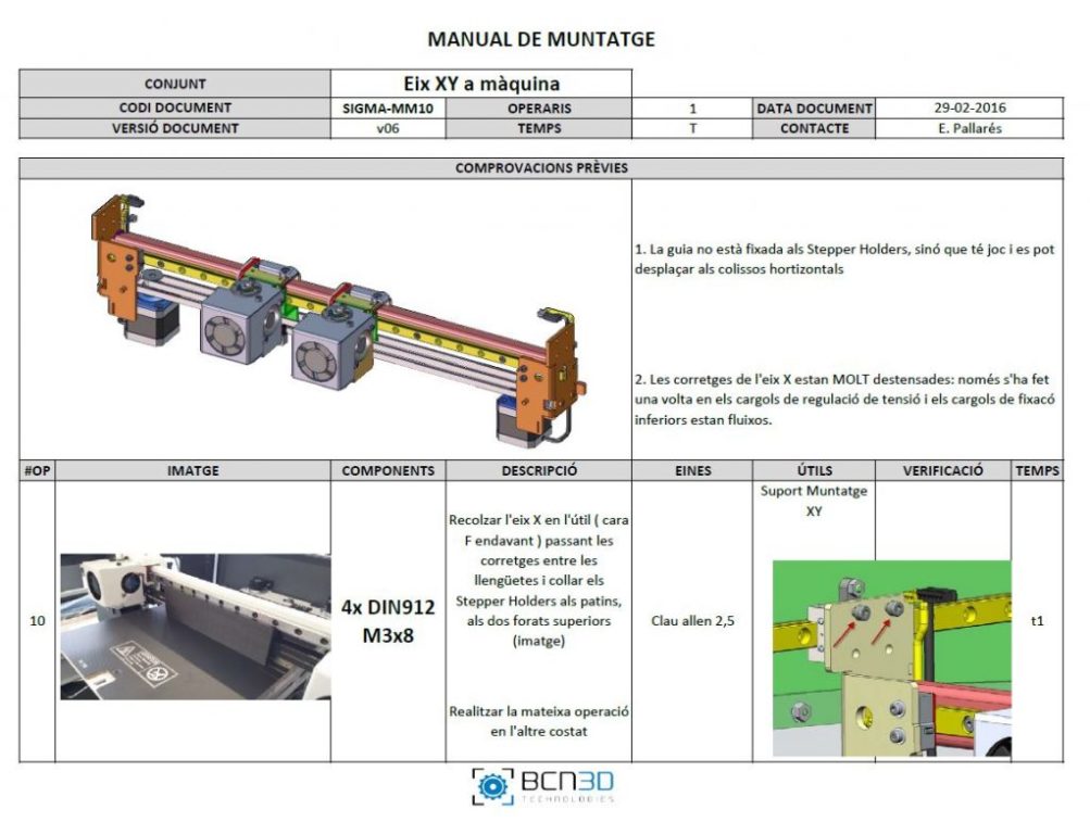
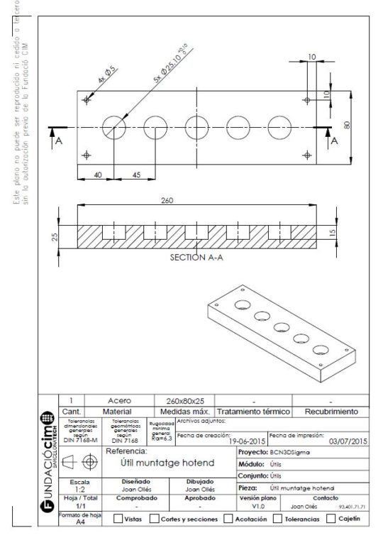
Jigs and Fixtures
The BCN3D Sigma is a high-precision equipment, so it is mandatory to assemble it meticulously. On the other hand, assembly time is a key factor we intend to reduce steadily. Both factors force us to design several jigs and fixtures to make sure the axes are properly aligned and the time needed to build a Sigma can be reduced day after day.
Quality Protocol
Once the Sigma is assembled, it’s time to verify it works perfectly. Every single printer undergoes a thorough Quality Protocol that checks its finish as well as its mechanical and electronic systems. Finally, Sigma prints some test parts for approximately 25h.