The importance of the build plate orientation when using Mesh Mapping
It is necessary to keep the build plate orientation when Mesh Mapping is enabled; due to the production process of the build plate, small undulations are formed across the surface of the glass making it not perfectly flat. These small undulations can affect the first layer adhesion and the end result of the surface on the bottom side.
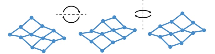
These undulations are irregular across the whole surface and because of this, to make sure that the Mesh Mapping does not need to be set more than once and to avoid issues derived from the wrong placement of the glass, it is important to always maintain the same orientation.
How to maintain the correct orientation of the build plate
To maintain the correct orientation of the build plate, it is necessary mark one of the sides. For this purpose, the central backside of the plate can be used.
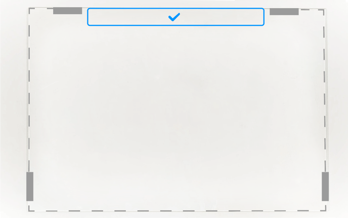
- It is recommended to place a sticker inside the safe area and on the upper side of the glass, this is to avoid any effects on the build plate flatness that a sticker on the bottom side of the glass could create.
- In the case that stickers are unavailable, a permanent marker can be used. It is important to keep in mind that these marks can disappear with time if the glass is cleaned with products other than water.
- Note: The available safe area is 300mm x 25mm.
Possible errors when changing the orientation
If the orientation of the build plate is changed after setting the Mesh Mapping, the following issues can appear depending on the situation of the differences between the build plate and the Mesh Mapping settings, here is a list of issues:
1. Mid-air print or lack of adhesion
Even though the differences in height between the normal plane and the mesh mapping are no bigger than 1mm, when the Mesh Mapping setting has a set peak on that area and the build plate is a valley instead, this can create a difference in height big enough to cause these problems.
- Warping: This problem is one of the most common ones when there is a lack of adhesion on the part. When the difference in height is big enough this lack of adhesion makes it so these parts present warping.
- Partial or total loss of the print: in the case that the part itself is not properly adhered to the build plate, it can lead to a loss of this part or the entire print if it gets unstuck during the printing process.
2. Scratch or impact with the build plate
This is the opposite situation from the issues presented above, when the Mesh Mapping sets a valley and the glass is a peak instead, the difference in height can be zero or even less than that. In this case, the hotend would hit the build plate when moving through this spot.
- Hotend clogged: this is an issue derived from the fact that the hotend is unable to extrude filament while grazing against the glass. This causes the filament to exit the only way it can which is up, creating a clog inside the nozzle.
- Build plate chipping: when the hotend is not extruding filament, it moves faster around the print in order to reduce the total time of the print. If the nozzle scratches or hits the build plate when going at this speed (150mm/s or more) it can chip the build plate.
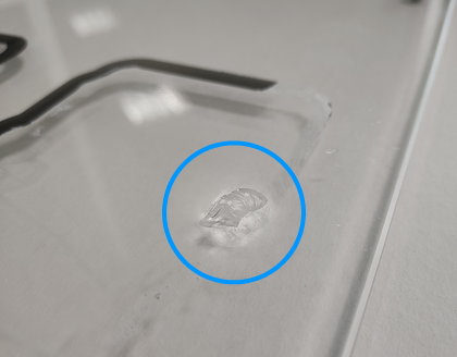
- Print deformation: this issue appears on the upper layers of the print and it has a very high chance if the combing mode has been enabled. This is caused when the hotend hits on the part itself, resulting in a deformation of the part (because of the temperature of the nozzle) and it can lead to the part being unstuck from the build plate itself.
- Reduction of moving parts lifespan: even though the structure of the printing head is made to resist a good amount of hits, a continued occurrence of these can lead to the rail bearing losing its adjustment and creating wobble on the Z axis.
3. Issues related to dimensional accuracy and its compensation
The discrepancies between the Mesh Mapping values and the build plate undulations will deform the bottom side of the print which results in imperfections related to the measurements of the print.