Warning! This is an advanced guide, if you have any questions about it feel free to ask us by filling up this form.
If you find any strange behavior in the movement of your BCN3D Sigma, it's likely that the stepper motor driver boards are not sending the correct signals. Checking their voltage is a good way to see if that's the issue or not.
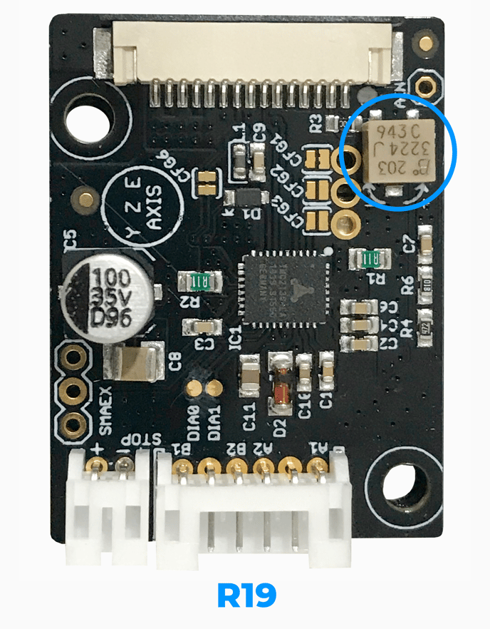
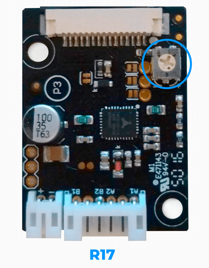
On all drivers there's a built-in potentiometer that can be adjusted to increase or decrease the voltage. This is marked with a blue circle in the pictures below. Depending on the model you have, the drivers have different settings:
Note: The driver has to be connected to the printer or to an external power supply in order to check and calibrate their voltage.
R17 Drivers:
1. With the tester set on DC Voltage mode, put a pin on the GND connector (Blue) and the other to the voltage output (Red)
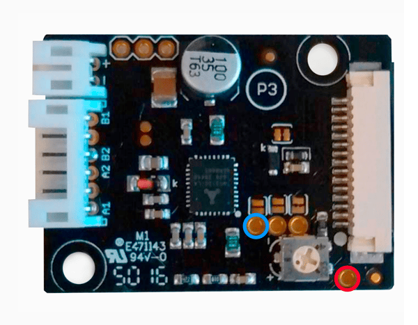
2. Depending on the value shown in the multimeter's display, adjust the potentiometer with a fine flat or philips screwdriver until the following values are reached:
| Driver Type | Voltage Value |
| X motor | 1.2V |
| Y motor | 1.4V |
| Z motor | 1.4V |
| Extruder Motor | 1.4V |
Note: The tolerance for these settings is ±0.01V.
Tip: You can unscrew the drivers from their place while the flat cables are connected to have better access to them and make the checking easier.
R19 Drivers
1. With the tester set on DC Voltage mode, put a pin on the GND connector (Blue) and the other to the voltage output (Red)
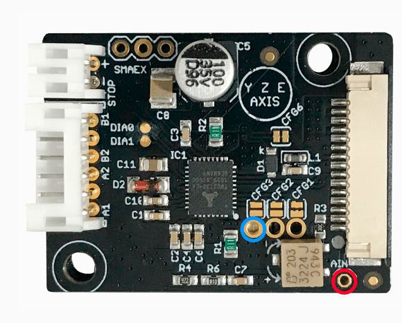
2. Depending on the value shown in the multimeter's display, adjust the potentiometer (it has a silver-colored, little screw on its side) with a watchmaker screwdriver until the following values are reached:
| Driver Type | Voltage Value |
| X motor | 1.2V |
| Y motor | 1.4V |
| Z motor | 1.4V |
| Extruder Motor | 1.4V |
Note: The tolerance for these settings is ±0.01V.
Tip: You can unscrew the drivers from their place while the flat cables are connected to have a better access to them and make the checking easier.
Conclusions:
If you see the reading is 5.00V or 0.00V, the driver board should be replaced, learn how to do it in the following links:
Replace the Extruder motor driver
Forum Community
This article doesn't fix your issue? Check out our forum community for more info about this.
It's important to keep your printer in good shape to make the most out of it. In this chart, you can find a list of the extruder maintenance procedures and how frequently these should be done. Maintenance Plan
![]() Take your e-waste to a certified recycler. Check how we do it in BCN3D.
Take your e-waste to a certified recycler. Check how we do it in BCN3D.
|
You can help improve the BCN3D Knowledge Base. If you feel there are guides that we are missing or you found any error, please use this form to report it. Report form :) |


