Find your model
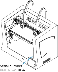
Select the model of your printer by clicking on the corresponding button according to the last 4 digits of the serial number.
If you can't find the serial number, click on the following article:


Sigma Series Mesh Mapping
D25 Before 0381
For more information about Mesh Mapping, continue reading...
Sigma Series Mesh Mapping
D25 After 0381
For more information about Mesh Mapping, continue reading...
How it works
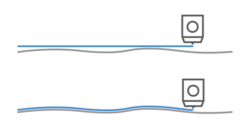
This functionality has been developed to greatly improve the adhesion of the first layer by compensating the build plate undulations with Z axis movements during the print. You can see an example on the following image:
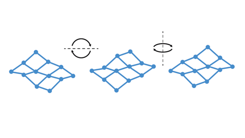
It is very important to maintain the build plate orientation if you want to use this new feature since the small undulations on the glass are different on each part, as you can see in the following image. It is recommended to mark your plate in some way to keep the same orientation even after removing the build plate.
In the following article you will find some important information regarding orienting the printing surface and identifying the correct position:
Mesh Mapping: Printing surface orientation
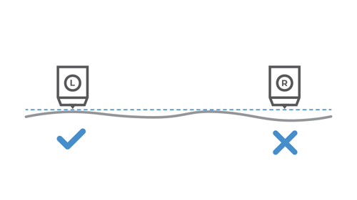
Mesh Mapping is not compatible with Duplication and Mirror mode prints since the Z-axis is unable to compensate both printing heads at once. This feature will be automatically disabled during prints in these modes.
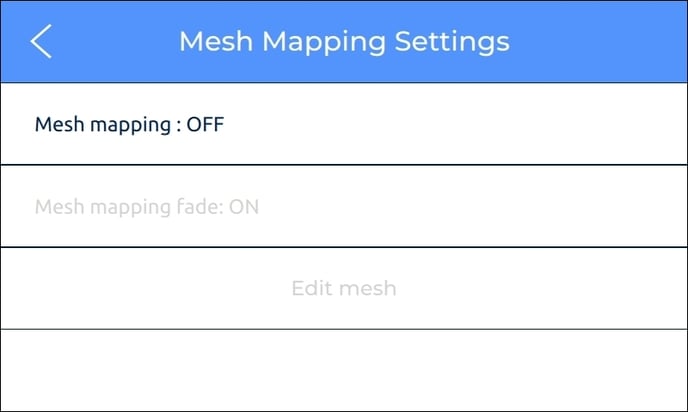
Mesh Mapping settings
This mode can be disabled at any time under the Utilities/Calibration/Mesh Mapping/Mesh Mapping Settings menu.
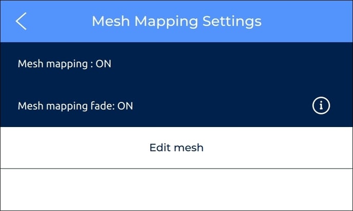
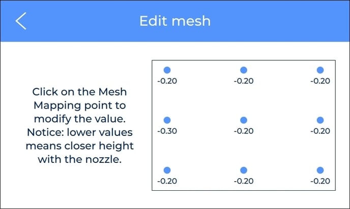
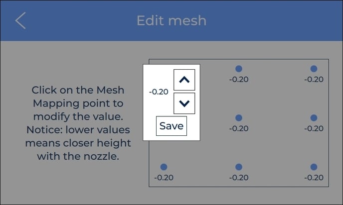
On this menu you can click on Edit mesh to manually tweak any of the nine spots by clicking on them, this is only recommended for advanced users. The process is similar to the Manual Offset Adjustment for the Z-axis offset.
Mesh mapping fade option
On the Mesh Mapping Settings menu, you can also enable and disable the Fade option which is enabled by default and recommended for most prints.
With the fade option enabled, the print will equalize the heights of the entire glass after a few layers to completely flatten the print. You can see how Fade works in the following image.
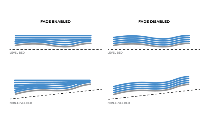
The following article explains the operation in detail as well as the advantages of the fade option: Mesh Mapping: Fade option
Forum Community
Need more tips? Check out our forum community for more info about this.
It's important to keep your printer in good shape to make the most out of it. In this chart, you can find a list of the extruder maintenance procedures and how frequently these should be done.
Maintenance Plan (Sigma Series)
![]() Take your electronic rights to an authorized service. Check how we do it at BCN3D
Take your electronic rights to an authorized service. Check how we do it at BCN3D

|
You can help improve the BCN3D Knowledge Base. If you feel there are guides that we are missing or you found any error, please use this form to report it. Report form :) |